vulcan-080703
Project and terrain context
Stage 01 of the Maptek Vulcan sequence: the geological interpretation is placed against the topographic surface to verify its position, extent and relationship with the ground surface.
ALBUM
All 18 records are shown below.
Stage 01 of the Maptek Vulcan sequence: the geological interpretation is placed against the topographic surface to verify its position, extent and relationship with the ground surface.
Stage 02 of the Maptek Vulcan sequence: the principal model components are assembled in a final three-dimensional view for technical review and communication.
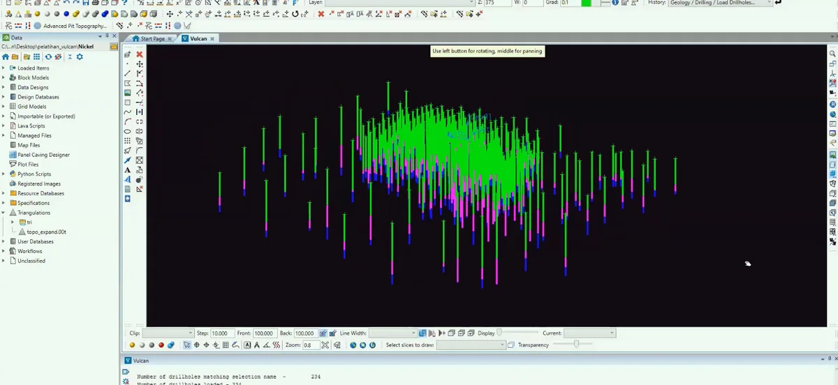
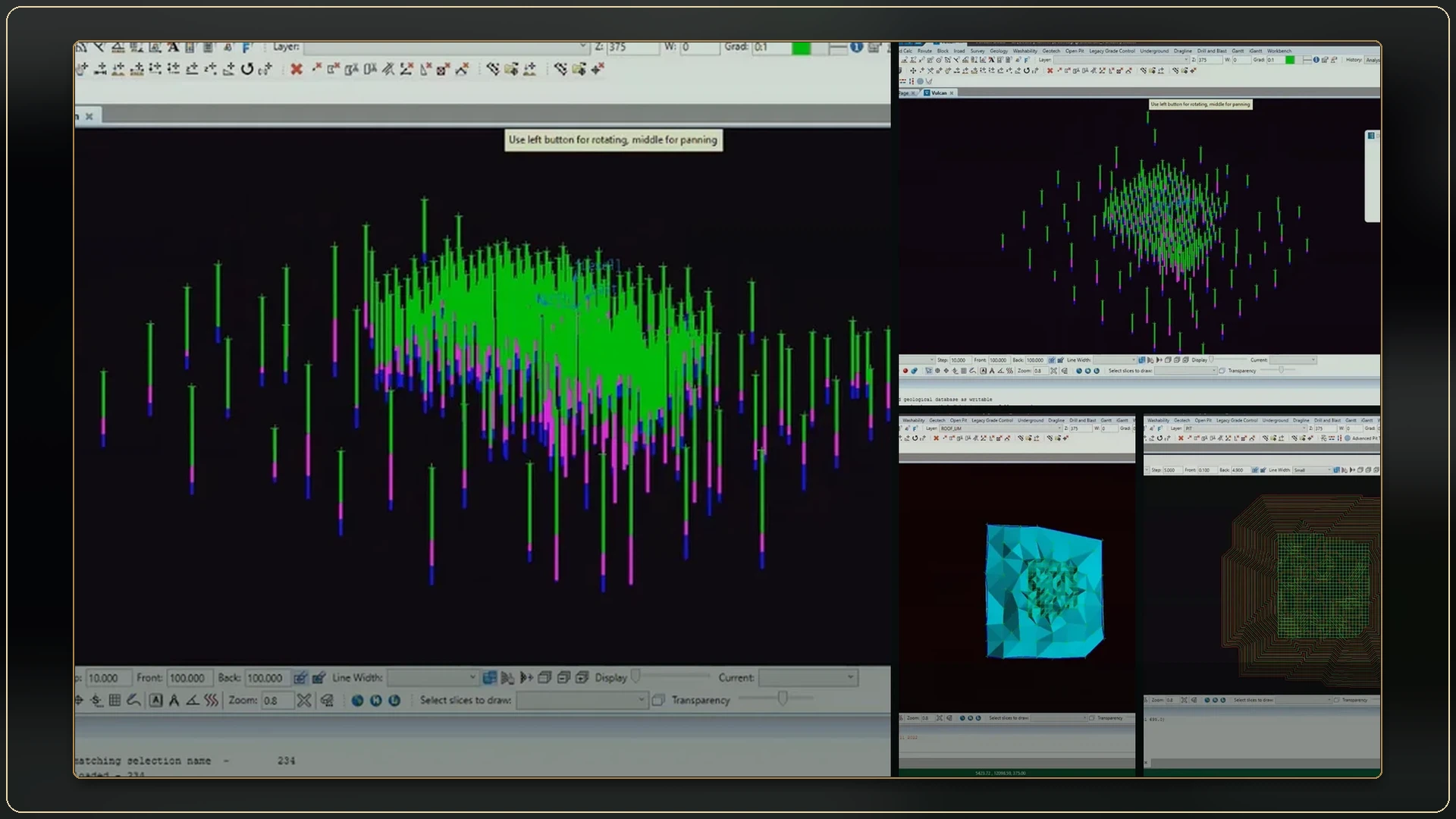
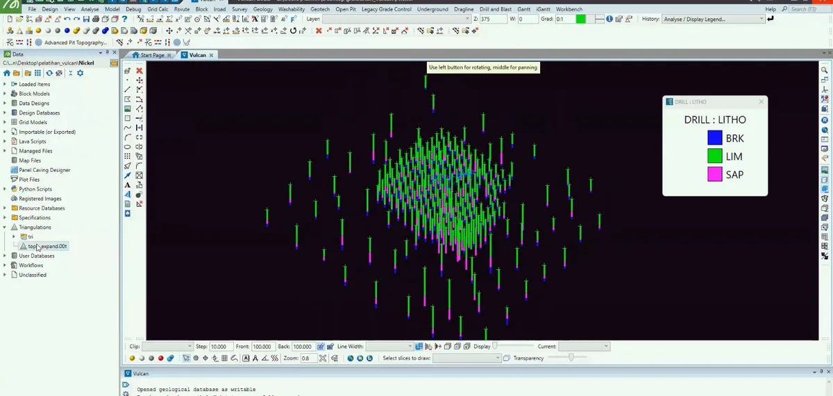
Stage 03 of the Maptek Vulcan sequence: drillholes and their coded intervals are displayed in three dimensions to confirm collar positions, trace orientation and the spatial distribution of geological control.
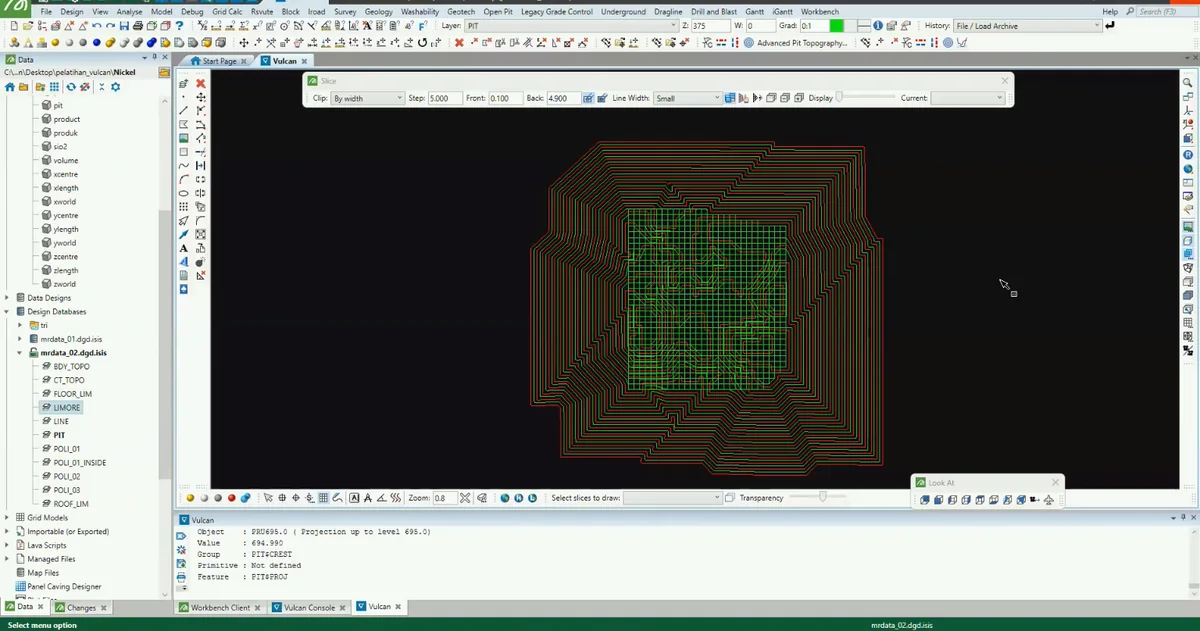
Stage 04 of the Maptek Vulcan sequence: interpretation strings are reviewed across the available sections, preserving the boundaries used to construct the geological domain.
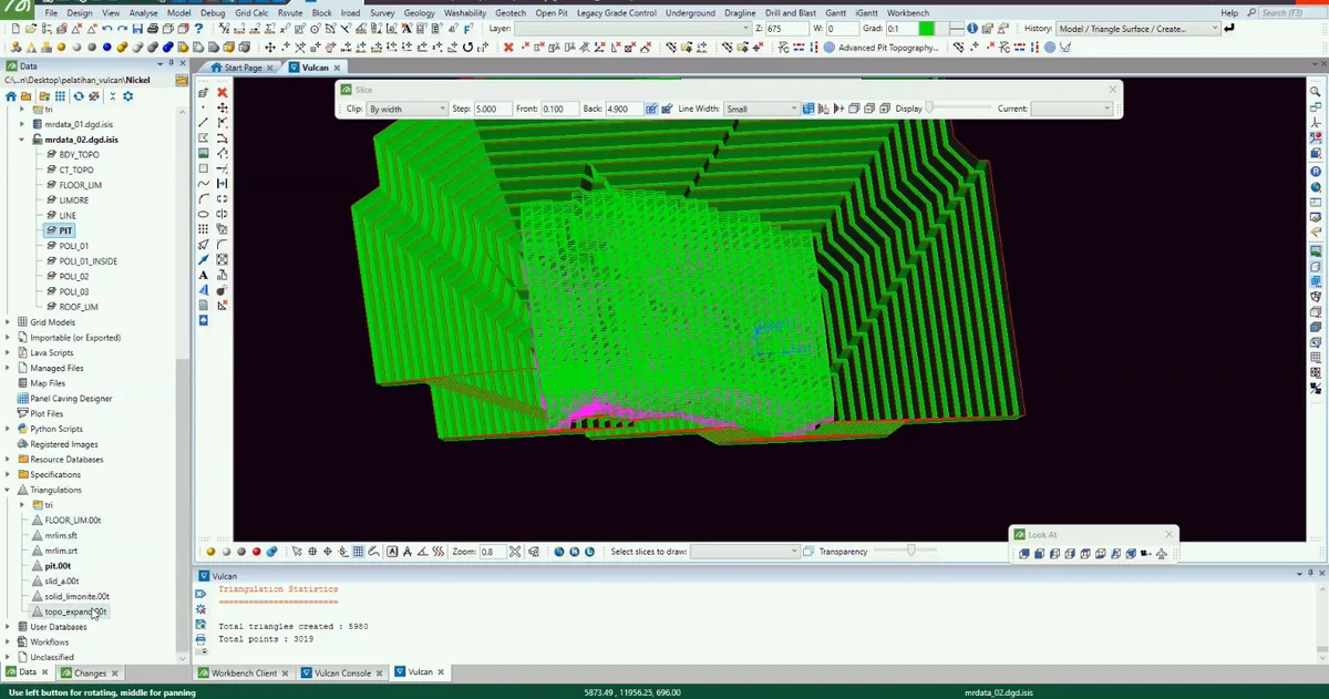
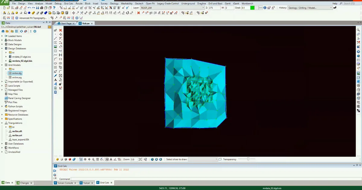
Stage 05 of the Maptek Vulcan sequence: the interpreted boundary is converted into a triangulated surface and inspected for continuity, edge behaviour and local geometric artefacts.
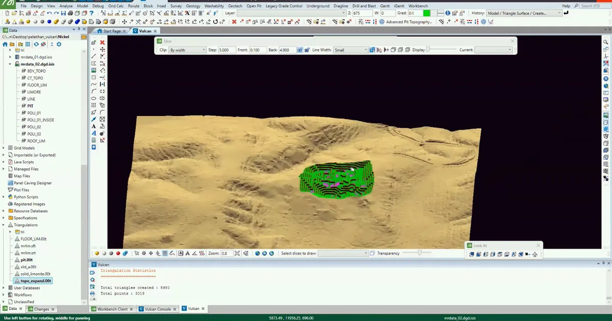
Stage 06 of the Maptek Vulcan sequence: the interpreted boundary is converted into a triangulated surface and inspected for continuity, edge behaviour and local geometric artefacts.
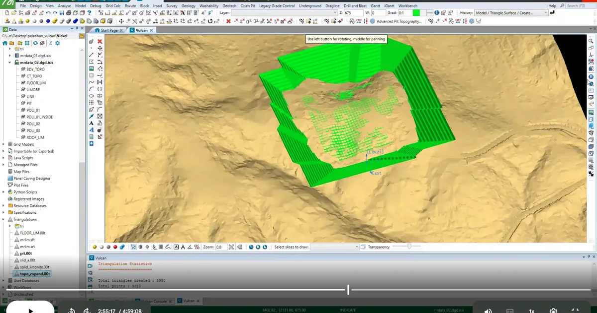
Stage 07 of the Maptek Vulcan sequence: bounding surfaces are joined into a closed geological solid that represents the interpreted three-dimensional domain.
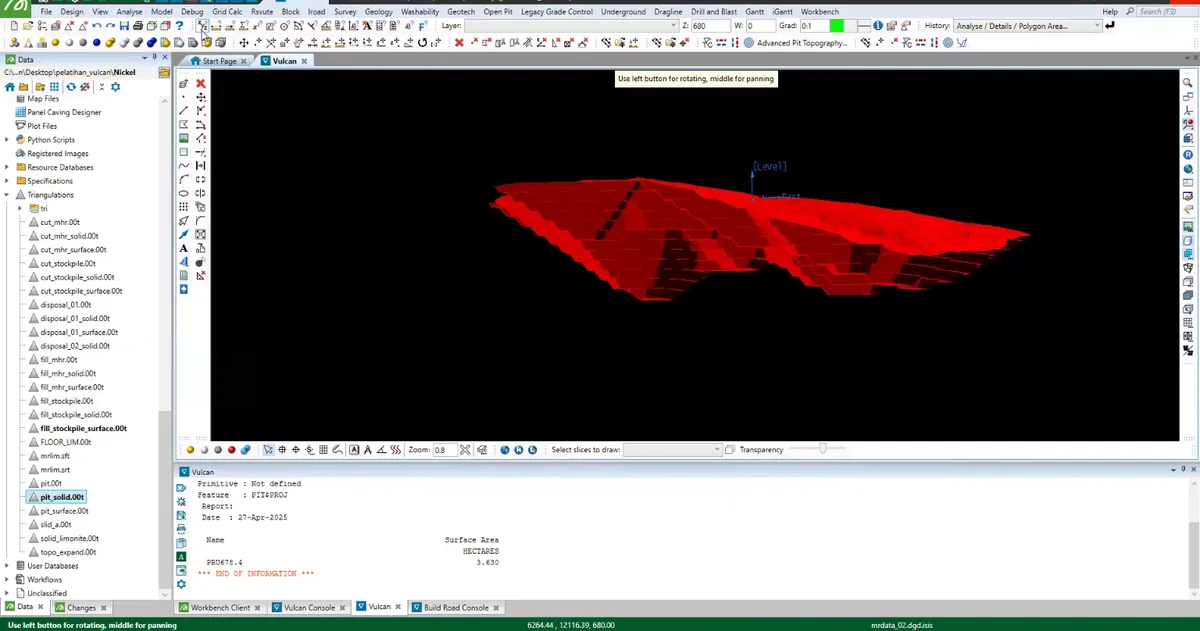
Stage 08 of the Maptek Vulcan sequence: the interpreted surfaces, solids or model cells are isolated and compared to check continuity, boundary conformity and internal consistency.
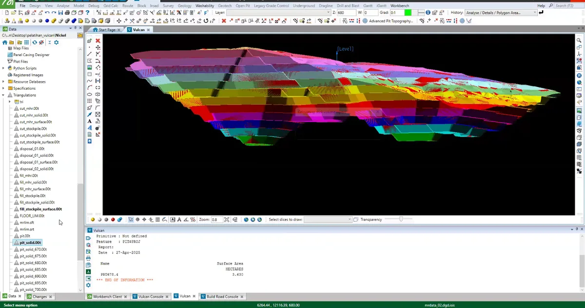
Stage 09 of the Maptek Vulcan sequence: a regular three-dimensional cell framework is generated across the interpreted domain, providing the structure required to store geological or quantitative attributes.
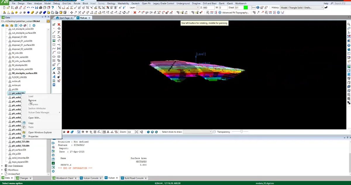
Stage 10 of the Maptek Vulcan sequence: the model is coloured by an assigned attribute so that spatial changes and domain boundaries can be inspected directly.
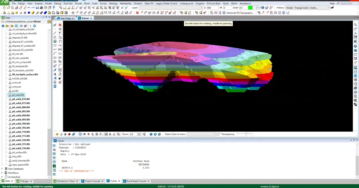
Stage 11 of the Maptek Vulcan sequence: the model is coloured by an assigned attribute so that spatial changes and domain boundaries can be inspected directly.
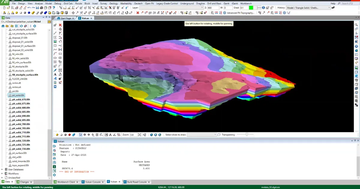
Stage 12 of the Maptek Vulcan sequence: a sectional cut exposes the internal relationship between the model, interpreted boundaries and the available geological control.
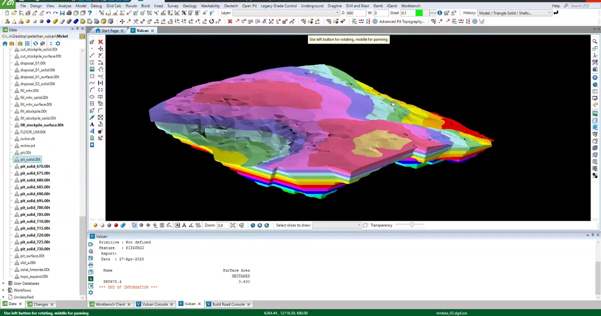
Stage 13 of the Maptek Vulcan sequence: the interpreted surfaces, solids or model cells are isolated and compared to check continuity, boundary conformity and internal consistency.
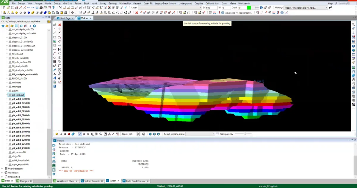
Stage 14 of the Maptek Vulcan sequence: the interpreted surfaces, solids or model cells are isolated and compared to check continuity, boundary conformity and internal consistency.
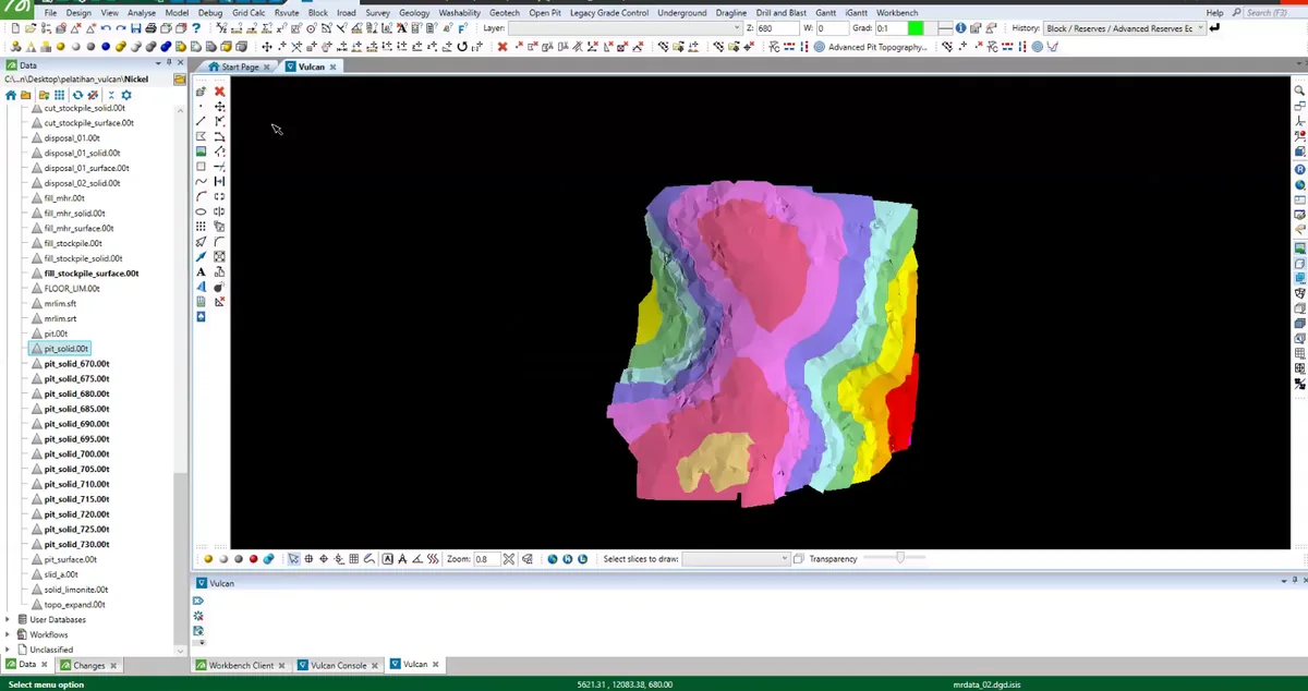
Stage 15 of the Maptek Vulcan sequence: the geological model is displayed with a design or volume boundary to examine the portion of the domain contained within the selected limit.
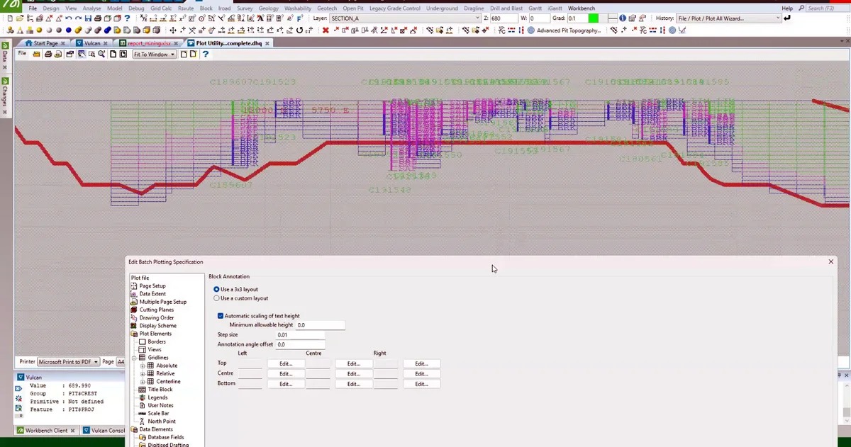
Stage 16 of the Maptek Vulcan sequence: the Maptek Vulcan project view displays the active geological objects at the integrated 3d scene stage.
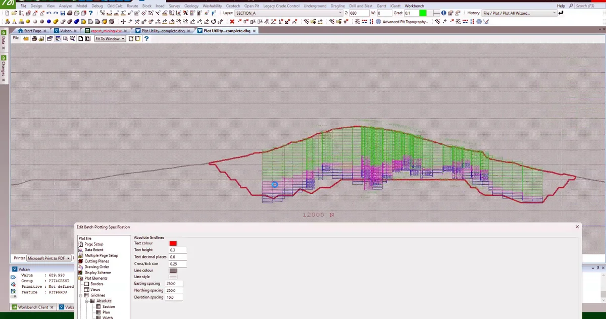
Stage 17 of the Maptek Vulcan sequence: the interpreted surfaces, solids or model cells are isolated and compared to check continuity, boundary conformity and internal consistency.
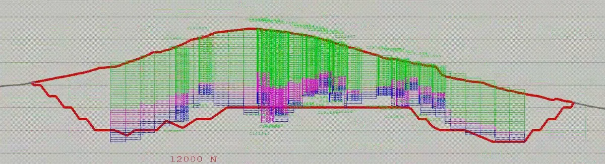
Stage 18 of the Maptek Vulcan sequence: the principal model components are assembled in a final three-dimensional view for technical review and communication.